Skip to content
recaplica

    One moment: security check

    Cloudflare wants to make sure you're not a robot. Tick the box below and your search will continue on its own.

    IT
    recaplica Monometric Axonometric Projection: What It Is and How to Draw It
    © 2026 Recaplica · recaplica.com — All rights reserved
    Home › Technology

    Monometric Axonometric Projection: What It Is and How to Draw It

    By Recaplica Newsroom · Updated on October 7, 2026

    What to print

    Page numbers appear when printing with default margins.

    Slides

    Choose a cut

    Flash10 slidesThe essential thread, to present in classFull14 slidesEvery chapter and the deeper detail

    Both come with speaker notes.

    Telegram channel
    recaplica Clear in 30 seconds, yours in 10 minutes.
    In 30 seconds Key points Deep dive Slides Myths Mind map Quiz Flashcards FAQ

    In 30 seconds quick read

    Monometric axonometric projection is an oblique projection used in technical drawing to represent a three-dimensional object on a flat sheet. In the scheme most common in Italian school curricula, the vertical axis stays upright, while the other two axes are drawn at 30° and 60° from the horizontal, with a 120° angle between the x-axis and the vertical axis. What sets it apart from cavalier axonometric projection is that the object's measurements are transferred onto all three axes without any reduction, at true scale. In Italian technical-drawing vocabulary the name carries some genuine uncertainty: some sources treat it as a synonym for isometric projection, while other textbooks present it as a separate category.

    Key Points

    • It's an oblique projection: in the classification used in Italian technical-drawing education, it doesn't belong among the orthogonal ones.
    • In the most common scheme the z-axis stays vertical, while the x-axis tilts 30° and the y-axis 60° from the horizontal.
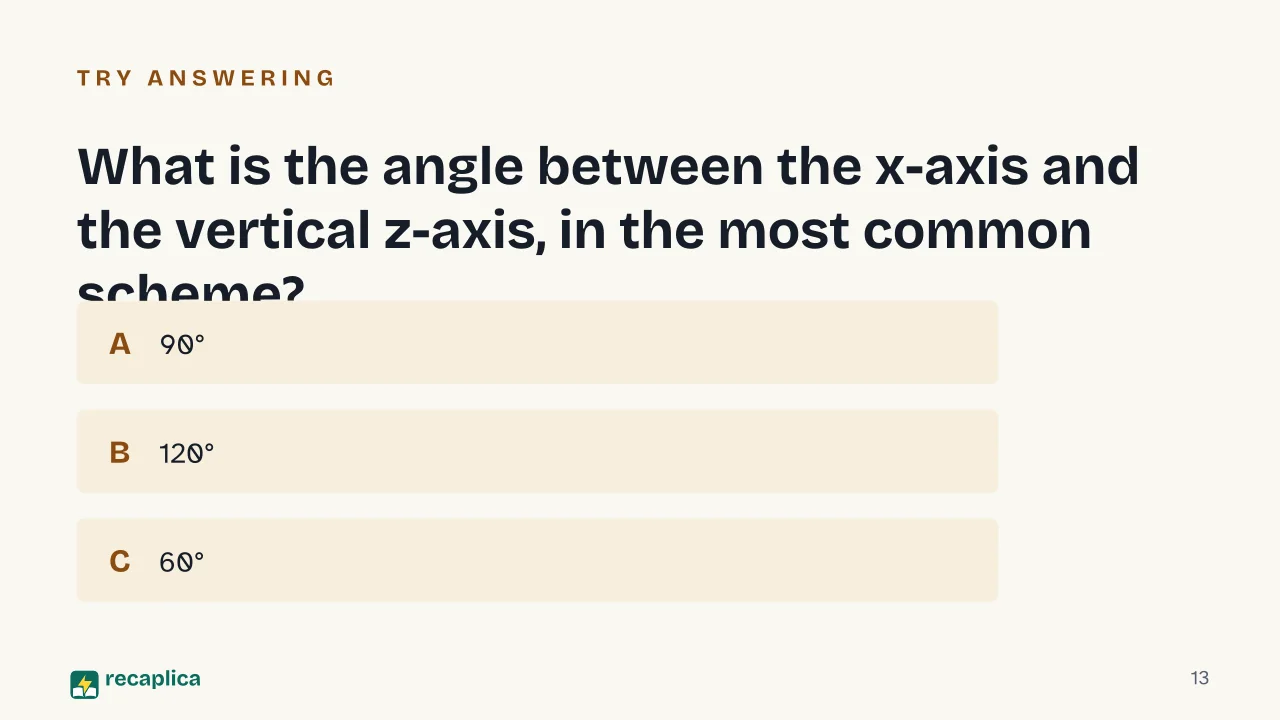
    • The resulting angle between the x-axis and the vertical z-axis measures 120°.
    • The object's measurements aren't reduced on any of the three axes: they stay true to the real size.
    • The name carries a school-level ambiguity: one academic source treats it as a synonym for isometric projection, while some textbooks keep the two separate.
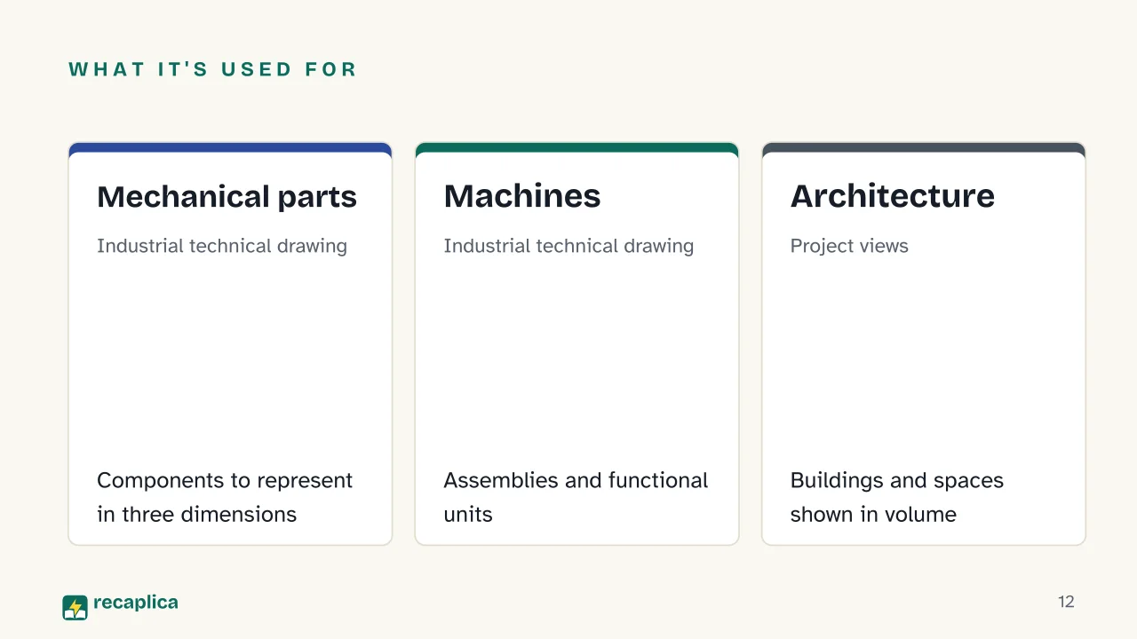
    • It's used to represent mechanical parts, machines, and also architectural projects.

    Deep Dive

    According to the Treccani Vocabolario online, axonometry is a projection method that transfers three-dimensional figures onto a plane: a way of drawing a three-dimensional object on a flat sheet without resorting to perspective. Monometric axonometric projection is one of the constructions this method makes possible, and Italian technical-drawing education classifies it as a type of oblique axonometric projection.

    Among axonometric projections, the monometric one has a specific reputation: it’s considered the simplest to execute, and that’s why it’s the most widespread in school technical drawing.

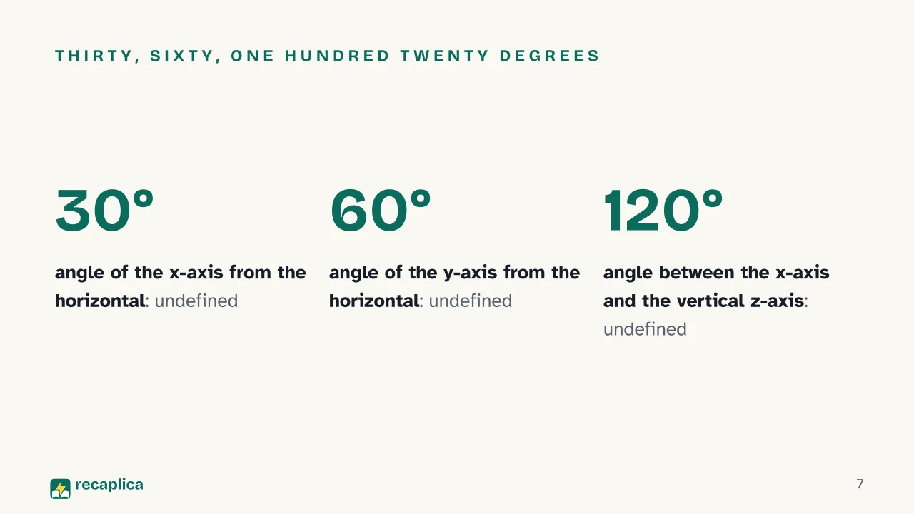
    The scheme most common in Italian schools is built like this: the z-axis stays vertical, while the other two axes tilt until they form angles of 30° and 60° with the horizontal line. The x-axis goes to 30°, the y-axis to 60°: they’re perpendicular to each other, and the angle that forms between the x-axis and the vertical z-axis measures 120°. Anyone who has already met axes and angles in Euclidean geometry, or coordinates in analytic geometry, will recognize the same language here, put to a different use: this isn’t about proving a theorem or locating a point, it’s about building a drawing.

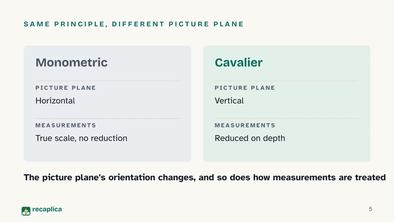
    Here the measurements aren’t touched: every side of the object is drawn at its true size on all three axes, a different treatment from cavalier axonometric projection, which reduces the measurements along the depth axis and uses a vertical picture plane instead of a horizontal one.

    Example in practice: a cube with a 4-centimeter side, drawn in monometric axonometric projection, has all three visible sides measuring 4 centimeters on the sheet, measured along their respective axes. The same cube in cavalier axonometric projection would have its depth side come out shorter, because that construction reduces it.

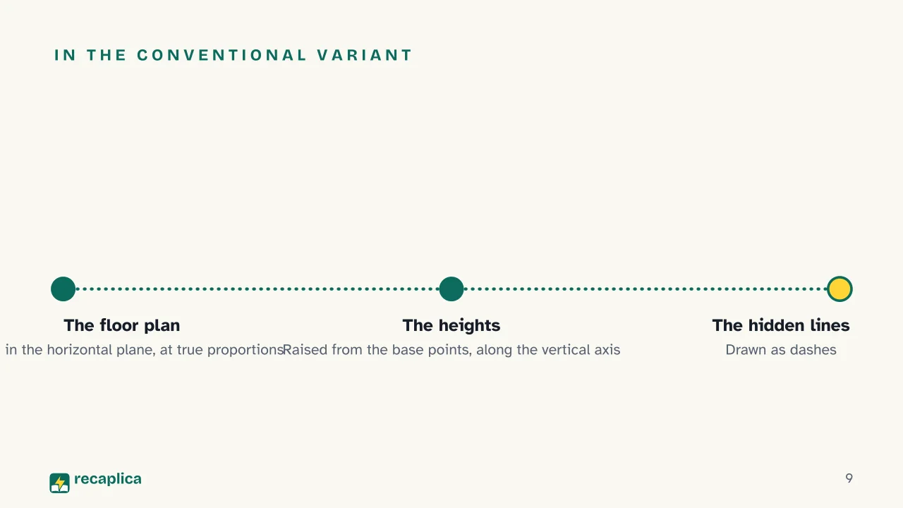
    A different source describes a variant called “conventional monometric,” derived from planometric axonometric projection: here the horizontal axes are perpendicular to each other (90°) and the vertical axis forms a 135° angle with each of the other two. The procedure starts by drawing the floor plan directly in the horizontal plane, meaning the base of the figure, already at its true proportions; the next step is raising the heights from the base points along the vertical axis. In the finished drawing, the lines that stay hidden behind the solid are drawn as dashes: it’s the same principle behind a model in solid geometry, where the base always comes before the rise in height.

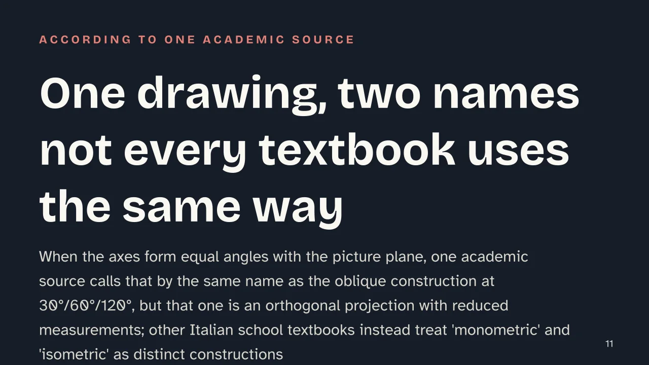
    A source of probable academic origin — a compilation that also reproduces an excerpt from a university text on architectural drawing — argues that when the three axes form equal angles with the picture plane, the projection can be called either “monometric” or “isometric”: they’re two names for the same construction, and in that case the three axes project onto the picture plane as segments of equal length. That source adds that Italian schools circulate programs and textbooks that treat the two terms as separate things, even though in its judgment that usage is incorrect. That overlap in names, though, concerns an orthogonal projection with reduced measurements: a different family from the oblique one at 30°/60°/120°, with no reduction, described above. In Italian school sources, then, the term “monometric” covers more than one construction. The Treccani Vocabolario doesn’t use the word “monometric” at all: it defines isometric projection as an orthogonal projection with the three units of measure equal to one another, and dimetric projection as one where only two of the three units coincide, with the third different. Anyone preparing for a test on this topic does well to check which version their own textbook follows, because both circulate in Italy.

    There’s also a more formal framework: the UNI EN ISO 5456-3:2001 standard sets the basic rules for axonometric representations in Italian and European technical drawing. In practice, this type of construction is often used for mechanical parts and machines, and the same axis structure also serves architectural views. The floor plan and the raising of heights can also be done with vector drawing software, which handles angles and proportions with automatic precision: the constructive principle, though, stays the same as the one traced by hand with a pencil, and anyone who wants to understand how that kind of file works can read about the difference between raster and vector images.

    Slide deck

    Slides ready to download and make your own in PowerPoint or Google Slides, with speaker notes. Pick the Flash cut or the Full one.
    Slide 1 of the presentation on Monometric Axonometric Projection: Monometric Axonometric ProjectionSlide 2 of the presentation on Monometric Axonometric Projection: Monometric and isometric: same drawing, two different names?Slide 3 of the presentation on Monometric Axonometric Projection: Angles, measurements, construction, nameSlide 4 of the presentation on Monometric Axonometric Projection: Chapter 01: What It IsSlide 5 of the presentation on Monometric Axonometric Projection: Same principle, different picture planeSlide 6 of the presentation on Monometric Axonometric Projection: Chapter 02: The Axes and the AnglesSlide 7 of the presentation on Monometric Axonometric Projection: Thirty, sixty, one hundred twenty degreesSlide 8 of the presentation on Monometric Axonometric Projection: Chapter 03: How It's BuiltSlide 9 of the presentation on Monometric Axonometric Projection: In the conventional variantSlide 10 of the presentation on Monometric Axonometric Projection: Chapter 04: One Name, Two UsesSlide 11 of the presentation on Monometric Axonometric Projection: One drawing, two names not every textbook uses the same waySlide 12 of the presentation on Monometric Axonometric Projection: What it's used for: Mechanical parts, Machines, ArchitectureSlide 13 of the presentation on Monometric Axonometric Projection: What is the angle between the x-axis and the vertical z-axis, in the most common scheme?Slide 14 of the presentation on Monometric Axonometric Projection: Now, for review
    Flash10 slidesThe essential thread, to present in classFull14 slidesEvery chapter and the deeper detail

    Common myths

    • ✗ Myth Monometric axonometric projection also reduces measurements along depth, like cavalier projection.

      ✓ Reality Reducing the depth axis is the defining trait of cavalier projection: in monometric projection, measurements stay true to the real object on all three axes.

    • ✗ Myth Monometric and isometric are always two different constructions, each with its own rules.

      ✓ Reality A source of probable academic origin places the two names on the same construction whenever the three axes come out equal with the picture plane (an orthogonal projection that reduces the measurements on all three axes). The same source adds, though, that some Italian school programs treat them as distinct categories rather than synonyms.

    • ✗ Myth There's only one angle scheme for monometric axonometric projection.

      ✓ Reality Another source describes a variant called 'conventional monometric,' with a different picture plane: horizontal axes at 90° to each other, 135° toward the vertical axis.

    Mind map

    Drag the background to move around and the nodes to reposition them; use − and + to collapse and expand branches.
    Customize
    Mind map: Monometric Axonometric Projection: What It Is and How to Draw It
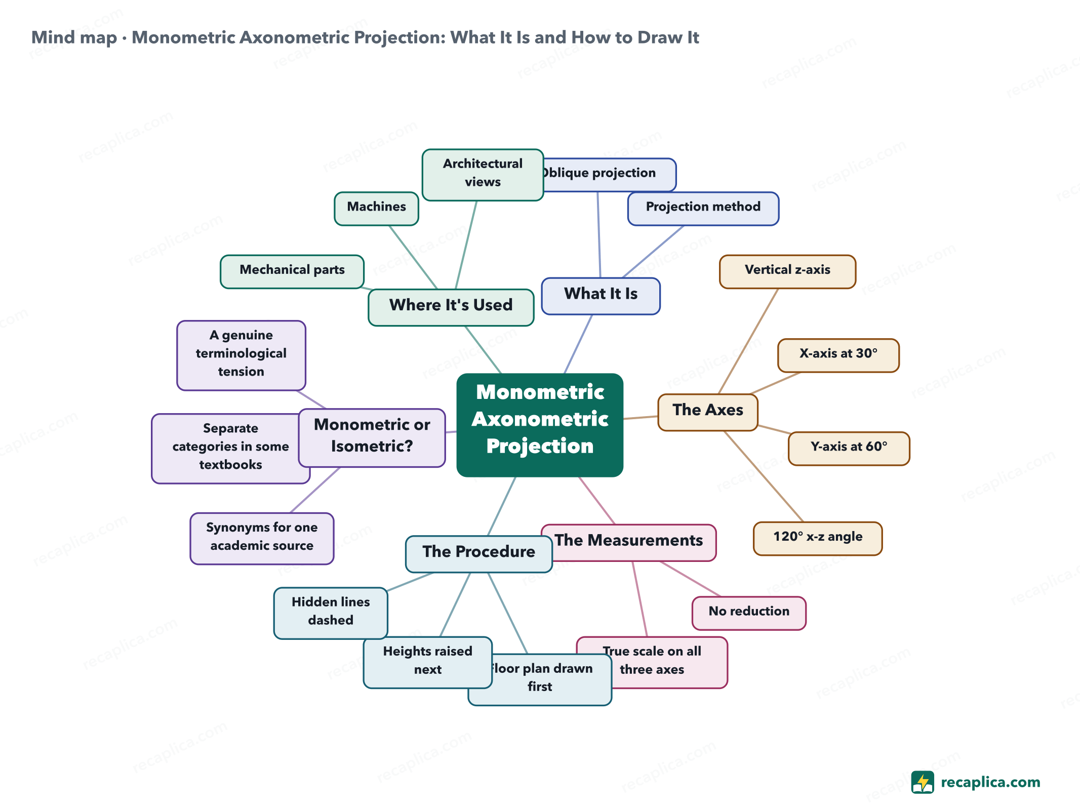
    • Monometric Axonometric Projection
      • What It Is
        • Oblique projection not orthogonal in the Italian school classification
        • Projection method transfers space figures onto a plane, Treccani Vocabolario definition
      • The Axes
        • Vertical z-axis
        • X-axis at 30° from the horizontal
        • Y-axis at 60° from the horizontal
        • 120° x-z angle
      • The Measurements
        • No reduction
        • True scale on all three axes
      • The Procedure
        • Floor plan drawn first in the horizontal plane, at true proportions
        • Heights raised next from the base points, along the vertical axis
        • Hidden lines dashed
      • Monometric or Isometric?
        • Synonyms for one academic source
        • Separate categories in some textbooks
        • A genuine terminological tension
      • Where It's Used
        • Mechanical parts
        • Machines
        • Architectural views

    Quiz: test yourself

    Answer the questions to check what you have learned: you get instant feedback and a short explanation.

    Grade 0/10 0/5
    1 According to the classification used in Italian technical-drawing education, what type of projection is monometric axonometric projection?

    One of the sources used in this Recap places monometric axonometric projection among oblique projections, meaning non-orthogonal, within Italian technical-drawing education.

    2 In the most common scheme, what is the angle between the x-axis and the vertical z-axis?

    With the x-axis drawn at 30° and the y-axis at 60° from the horizontal, the angle between the x-axis and the vertical axis works out to 120°.

    3 What happens to the object's measurements when they're transferred onto the three axes of monometric axonometric projection?

    This is the defining trait of this axonometric projection: no reduction on any axis, unlike cavalier projection.

    4 True or false: an academic source cited in this Recap states that Italian school textbooks always use 'monometric' and 'isometric' as interchangeable synonyms, with no exceptions.

    One of the academic sources used here notes that some Italian school programs and textbooks treat the two names as distinct constructions, even though it considers that usage incorrect.

    5 According to the source describing the 'conventional monometric' variant, what's the first step in constructing it?

    The procedure described for this variant starts from the base, drawn at its true proportions in the horizontal plane; only afterward do the heights go up.

    Answers: 1-A · 2-B · 3-C · 4-B · 5-B

    Flashcards

    Tap the card to flip it and check whether you remember the answer, then move to the next one.

    1 / 7

    Explain it in your own words

    The ultimate test: if you can explain it in simple words, you've truly understood it. Write your explanation, then compare it with the Recap.

    Your explanation is saved only on this device.

    Monometric axonometric projection is an oblique projection used in technical drawing to represent a three-dimensional object on a flat sheet. In the scheme most common in Italian school curricula, the vertical axis stays upright, while the other two axes are drawn at 30° and 60° from the horizontal, with a 120° angle between the x-axis and the vertical axis. What sets it apart from cavalier axonometric projection is that the object's measurements are transferred onto all three axes without any reduction, at true scale. In Italian technical-drawing vocabulary the name carries some genuine uncertainty: some sources treat it as a synonym for isometric projection, while other textbooks present it as a separate category.

    Frequently asked questions

    Are monometric and isometric axonometric projection the same thing?

    It depends on which source you consult, and which construction it's describing. A source of probable academic origin uses the two names as synonyms whenever the axes form equal angles with the picture plane, but that's an orthogonal projection, with the measurements reduced on all three axes, different from the oblique construction at 30°/60°/120° with no reduction; several Italian school textbooks, instead, keep 'monometric' and 'isometric' as two separate categories. In Italian school sources, 'monometric' doesn't always point to the same construction: before a test, it's worth checking which version your own textbook follows.

    What are the axis angles in monometric axonometric projection?

    In the scheme most common in Italian schools, the z-axis stays vertical, the x-axis tilts 30° from the horizontal, and the y-axis tilts 60°. The angle that results between the x-axis and the vertical z-axis is 120°.

    Does monometric axonometric projection reduce the object's measurements?

    No. In this type of axonometric projection, none of the three axes are ever reduced: every measurement stays identical to that of the real object. It's precisely this absence of reduction, together with the horizontal picture plane, that sets it apart from cavalier projection.

    What's the difference between monometric and cavalier axonometric projection?

    The picture plane changes orientation: horizontal for the first, vertical for the second. And only cavalier projection reduces measurements along the depth axis, while monometric projection keeps them true on every axis.

    What is monometric axonometric projection used for, in practice?

    It's used to represent mechanical parts and machines in industrial technical drawing, and the same axis scheme also works for architectural views.

    Sources

    • AliceAppunti, «Assonometria Monometrica e Assonometria Cavaliera»
    • AliceAppunti (blog), «Assonometria monometrica»
    • unmondoacolori.altervista.org, «Assonometria monometrica»
    • Treccani, Vocabolario online, voce «Assonometrìa»
    • UNI, norma UNI EN ISO 5456-3:2001
    • larapedia.com, «Disegno assonometria cavaliera isometrica e monometrica»

    Every Recap goes through an independent review before publication.

    Every evening, the day's new Recaps on our Telegram channel. Join the channel →

    Keep learning

    • Technology Isometric Drawing: What It Is and How to Draw It Isometric drawing represents a three-dimensional object on a flat sheet without distorting its proportions along any of the three axes. The coordinate axes always meet at 120° angles, and the scale is identical along each one — hence the name, which comes from the Greek for equal measure. It is built either by starting from a vertical axis and drawing the other two tilted 120° apart, or by rotating the object roughly 45° and then about 35° relative to the viewer. It is the most common type of axonometric projection in technical drawing, and it also shows up in video games and pixel art. Read the Recap →
    • Technology Axonometric Projection: Definition and How to Draw It Axonometric projection is the descriptive-geometry method for drawing a three-dimensional object on a flat sheet in a single view. Unlike perspective, parallel lines stay parallel, so distances can be measured straight off the drawing. Several variants exist, isometric, trimetric, dimetric, oblique (cavalier), which change the angles between the axes and how each one shortens the measurements. The type most used in school technical drawing is isometric, with 120° angles between the axes, built from an isometric scale that carries the correct lengths onto the paper. Engineers and architects also rely on it to show the shape and structure of a building in one diagram. Read the Recap →
    • Technology What Is Orthographic Projection? How to Draw an Object in Three Views Orthographic projection is how technical drawing shows a three-dimensional object using several flat views instead of one: a top view, a front view, and a side view. Each view comes from projecting the object onto a plane set at a right angle to the direction you're looking from, and together the three views carry enough information to reconstruct shape and size without guessing. The United States uses third-angle projection, which places each view on the same side as the face it shows; most of the rest of the world, including Europe, uses first-angle projection, which places it on the opposite side. The method traces back to Gaspard Monge's two-plane projection, written up in the eighteenth century and still the basis of geometric drawing today. Read the Recap →

    recaplica

    Clear in 30 seconds, yours in 10 minutes.

    Recaps Mind maps Request a Recap Telegram channel Mind map maker Our method About Privacy & cookies Legal notes & terms of use

    © 2026 Recaplica · A project by Curi S.r.l. — VAT IT05472000750

    Statistics, only if you say so

    To learn which Recaps help most we would use Google Analytics, with aggregate, anonymous data. It starts only with your OK, and you can change your mind anytime. Privacy policy