recaplica
Clear in 30 seconds, yours in 10 minutes.
In 30 seconds quick read
Axonometric projection is the descriptive-geometry method for drawing a three-dimensional object on a flat sheet in a single view. Unlike perspective, parallel lines stay parallel, so distances can be measured straight off the drawing. Several variants exist, isometric, trimetric, dimetric, oblique (cavalier), which change the angles between the axes and how each one shortens the measurements. The type most used in school technical drawing is isometric, with 120° angles between the axes, built from an isometric scale that carries the correct lengths onto the paper. Engineers and architects also rely on it to show the shape and structure of a building in one diagram.
Key Points
Axonometric projection is a descriptive-geometry method for showing a three-dimensional object on a flat surface, with all three dimensions visible in a single view.
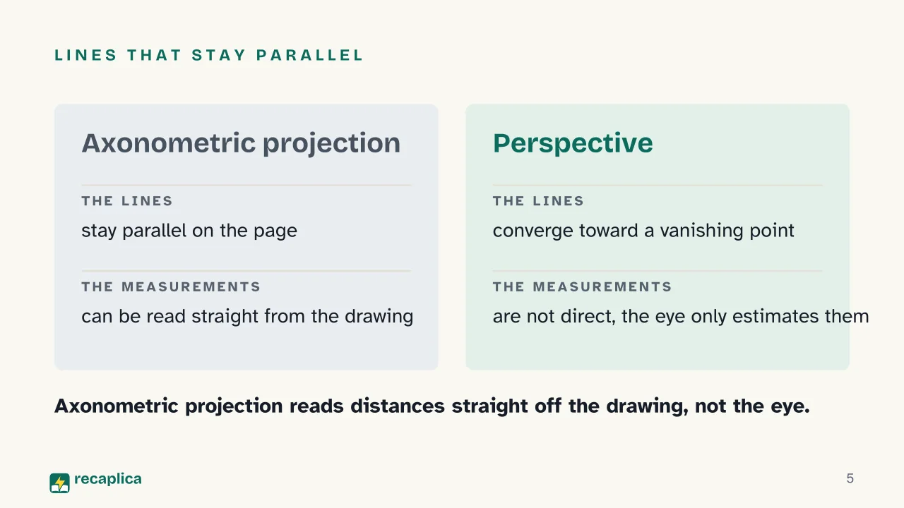
Unlike perspective, axonometric projection keeps parallel lines parallel, so measurements can be taken straight from the drawing.
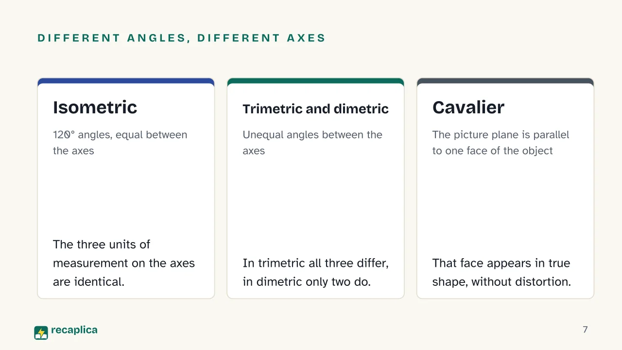
The main types are isometric (equal angles between the axes), trimetric and dimetric (unequal angles) and cavalier or oblique (one face shown in true shape).
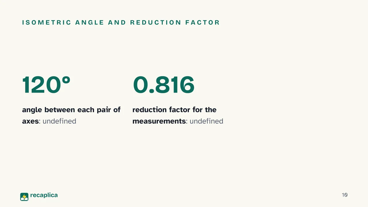
In isometric projection the three axes meet at 120° angles, with the two horizontal axes tilted 30° from the horizontal line.
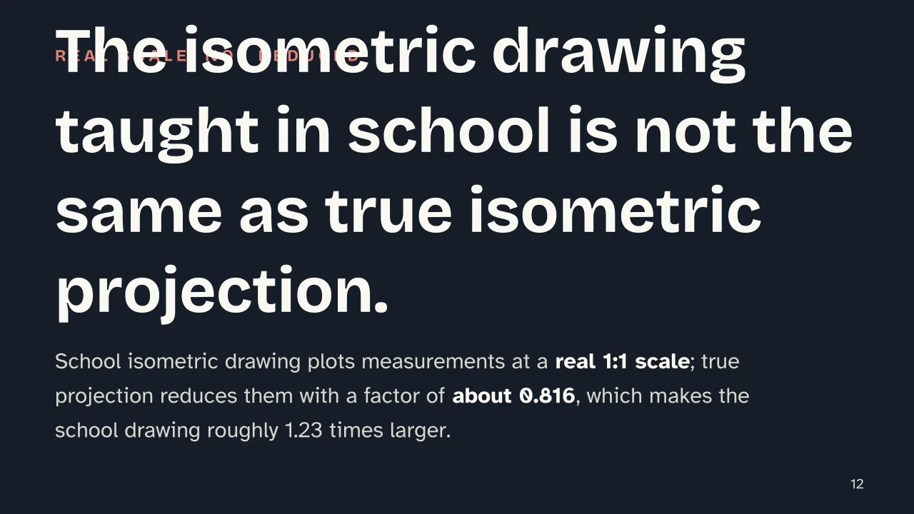
The isometric drawing taught in school plots measurements at true scale; true isometric projection shrinks them by a factor of about 0.816.
Beyond technical drawing, axonometric projection is used in architecture to show spaces and structures, including the exploded form that pulls components apart.
Key figures
120° In isometric projection the three axes meet at 120° angles, one of three ways axes can tilt relative to the picture plane. Source: NPTEL, Engineering Drawing
0.816 In true isometric projection, real-world measurements are multiplied by about 0.816, the cosine of 35°16', to get the lengths plotted on the axes. Source: NPTEL, Engineering Drawing
Deep Dive
Axonometric projection is a graphical method from descriptive geometry. It is used to draw three-dimensional objects on a flat sheet, showing the whole shape in a single view.
The difference from perspective comes down to how lines behave on the page. In perspective, lines that are parallel in reality converge toward a vanishing point, and objects further away look smaller: that is how the eye actually sees the world. Axonometric projection works differently: parallel lines stay parallel on the page and sizes do not shrink with distance, so distances can be measured straight off the drawing. Orthographic projection solves the problem of showing three dimensions by splitting the object into several separate views, plan, elevation, side view; axonometric projection brings them all together into a single drawing.
There is more than one way to build an axonometric drawing, depending on how the reference axes tilt relative to the sheet. In isometric projection the three reference planes form equal angles with the picture plane, so the units of measurement on the three axes come out identical. In trimetric projection all three angles differ from one another; in dimetric projection only two differ, and the units of measurement shrink by a different amount along each axis. In cavalier projection, a type of oblique axonometric drawing, the picture plane is parallel to one of the object’s faces, which therefore appears in true shape.
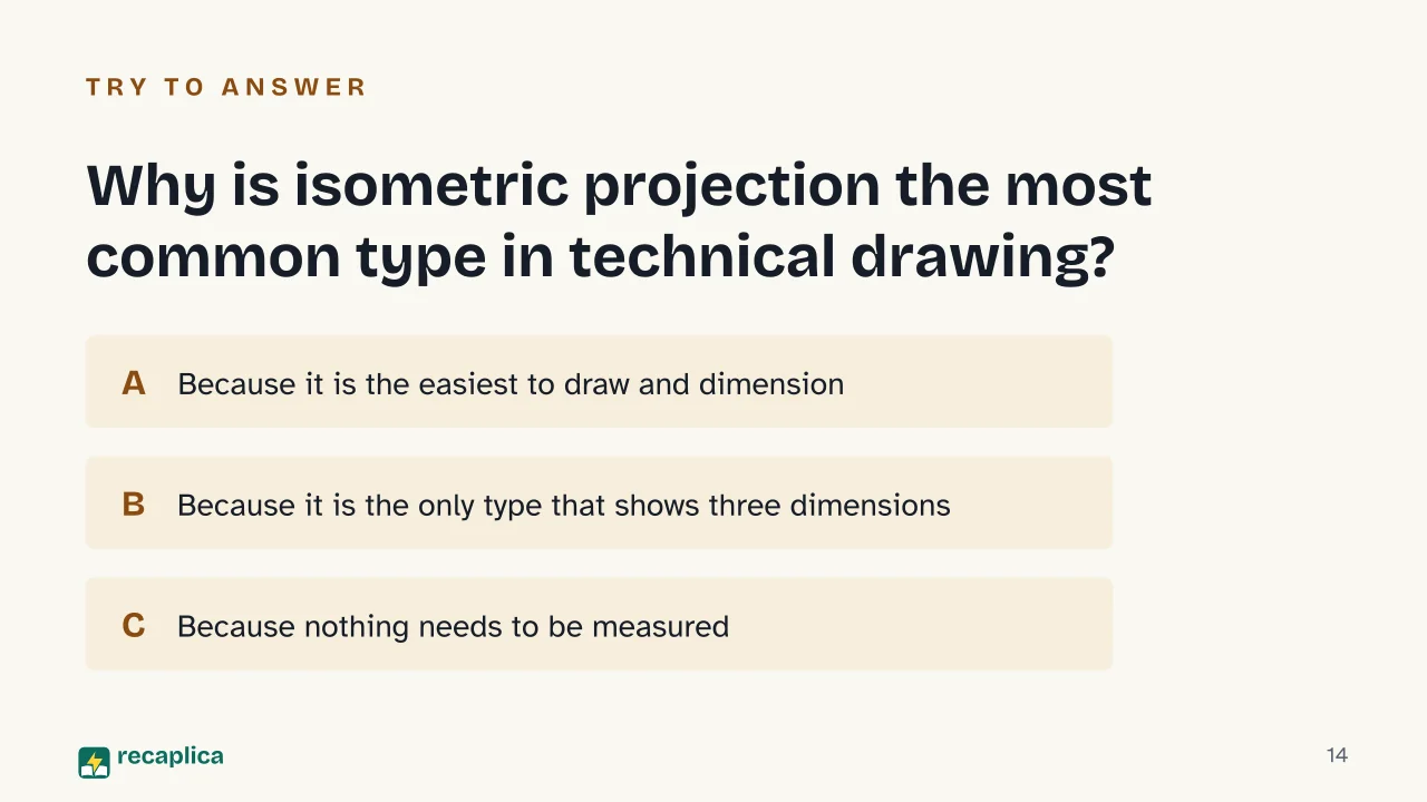
The type most common in technical drawing courses is isometric projection: NPTEL calls it the easiest to draw and dimension, thanks to its equal angles. The two horizontal axes are drawn tilted 30° from the horizon line, one to the right and one to the left; the third axis stays vertical, which leaves 120° angles between each pair of axes. In true isometric projection, the object’s real measurements are not transferred with an ordinary ruler: they come from an isometric scale, built by tilting a normal scale 45° and projecting its marks vertically onto a line at 30°. The correct lengths only apply along directions parallel to the axes, not along any line drawn at random. In school practice, isometric drawing is used far more often: the same 120° angles, but measurements plotted at a real 1:1 scale, skipping the isometric scale altogether. The result comes out roughly 1.23 times larger than true isometric projection, which applies a reduction factor of about 0.816, the cosine of 35°16’. Technical drawing almost always favours the simpler isometric drawing for this practical reason.
Practical example: to draw a cube in isometric projection, start from a point that will be the corner closest to the viewer. From there, trace the three axes: one straight up, and the other two tilted 30° upward, one to the left and one to the right. Each edge of the cube is plotted along one of the axes, at real scale if drawing an isometric drawing, and the faces are completed by joining the points with lines parallel to the axes.
The objects best suited to this kind of exercise are basic geometric solids, cubes, prisms, pyramids, because their regular edges and faces make it easy to check angles and proportions; anyone who needs a refresher on their properties can start from the page on solid geometry.
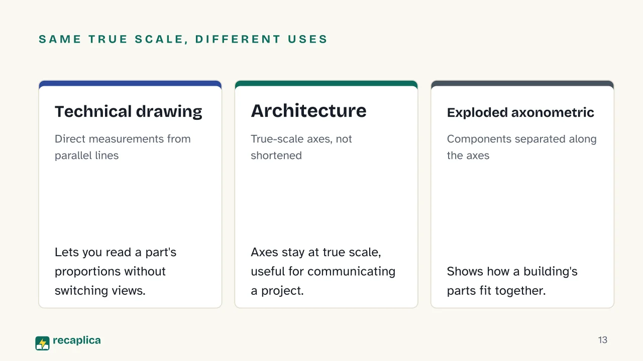
Outside the classroom, axonometric projection remains a working tool. In architecture, it is used to represent three-dimensional buildings on a flat surface while keeping the three axes at true scale, so that whoever reads the drawing gets an accurate sense of the spaces, the structure and the design intent, a use that fits within the wider field of visual communication for building projects. A variant common in this field is exploded axonometric drawing, which separates a building’s or a structure’s components along the axes, to show how the individual parts fit together.
Slide deck
Slides ready to download and make your own in PowerPoint or Google Slides, with speaker notes. Pick the Flash cut or the Full one.
✗ Myth Many people think axonometric projection and perspective are the same thing.
✓ Reality In axonometric projection parallel lines stay parallel and measurements can be read straight off the drawing; in perspective, lines converge toward a vanishing point and objects shrink with distance, because perspective mimics the way the eye actually sees.
✗ Myth Many people think the isometric drawing used in school textbooks is a true isometric projection.
✓ Reality School isometric drawing plots measurements at a real 1:1 scale, while true isometric projection applies a reduction factor of about 0.816: the school drawing comes out roughly 1.23 times larger, but it is preferred because it is simpler to produce.
✗ Myth Many people think cavalier projection is the most common type in technical drawing.
✓ Reality Isometric is the most common type: its equal angles between the axes make it, according to NPTEL, the easiest choice for drawing and dimensioning a part; cavalier projection stays useful when one face of the object needs to appear in true shape.
Mind map
Drag the background to move around and the nodes to reposition them; use − and + to collapse and expand branches.
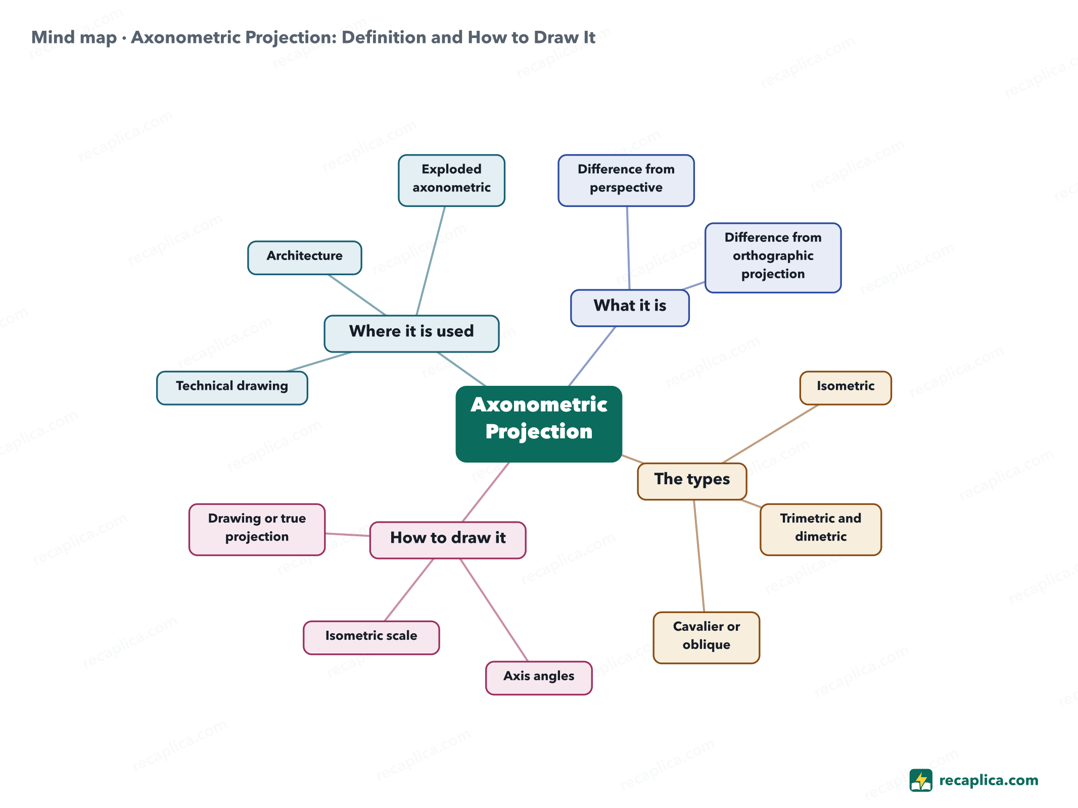
What it isA descriptive-geometry method for the flat page
Difference from perspectiveparallel lines stay parallel
Difference from orthographic projectionone view instead of several
The types
Isometric120° angles, equal between the axes
Trimetric and dimetricunequal angles between the axes
Cavalier or obliquethe picture plane is parallel to one face
How to draw it
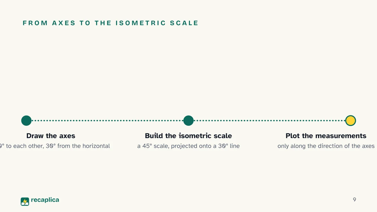
Axis angles120° to each other, 30° from the horizontal
Isometric scalea 45° scale projected onto a 30° line
Drawing or true projectionreal scale, or reduced by 0.816
Where it is used
Technical drawingdirect measurements from parallel lines
Architecturespaces, structure, design intent
Exploded axonometriccomponents pulled apart along the axes
Quiz: test yourself
Answer the questions to check what you have learned: you get instant feedback and a short explanation.
Grade0/100/5
Answers: 1-A · 2-A · 3-B · 4-A · 5-A
Flashcards
Tap the card to flip it and check whether you remember the answer, then move to the next one.
1 / 7
Explain it in your own words
The ultimate test: if you can explain it in simple words, you've truly understood it. Write your explanation, then compare it with the Recap.
Your explanation is saved only on this device.
Axonometric projection is the descriptive-geometry method for drawing a three-dimensional object on a flat sheet in a single view. Unlike perspective, parallel lines stay parallel, so distances can be measured straight off the drawing. Several variants exist, isometric, trimetric, dimetric, oblique (cavalier), which change the angles between the axes and how each one shortens the measurements. The type most used in school technical drawing is isometric, with 120° angles between the axes, built from an isometric scale that carries the correct lengths onto the paper. Engineers and architects also rely on it to show the shape and structure of a building in one diagram.
Frequently asked questions
What is axonometric projection in technical drawing?
It is a descriptive-geometry method that represents a three-dimensional object on a flat surface in a single view, with parallel lines staying parallel on the page.
What is the difference between axonometric and orthographic projection?
Orthographic projection splits an object into several separate views, such as plan and elevation; axonometric projection brings all three dimensions together into one drawing.
How is axonometric projection used in engineering drawing?
Engineering drawing favours isometric projection because its equal 120° angles make a part easier to draw and dimension than with the other types; the resulting single view still lets you read proportions directly, without switching between separate orthographic views.
How is axonometric drawing used in architecture?
Architects use it to represent buildings while keeping the axes at true scale, which helps readers see how a building's spaces and structure fit together at a glance; the exploded variant pulls a building's components apart along the axes to show how they are assembled.
How do you build an isometric scale?
Tilt an ordinary measuring scale 45° and project its marks vertically onto a line tilted 30°: the resulting lengths are the ones to plot on the axes of a true isometric projection.
Every Recap goes through an independent review before publication.
Statistics, only if you say so
To learn which Recaps help most we would use Google Analytics, with aggregate, anonymous data. It starts only with your OK, and you can change your mind anytime. Privacy policy