Skip to content
recaplica

    One moment: security check

    Cloudflare wants to make sure you're not a robot. Tick the box below and your search will continue on its own.

    IT
    recaplica Isometric Drawing: What It Is and How to Draw It
    © 2026 Recaplica · recaplica.com — All rights reserved
    Home › Technology

    Isometric Drawing: What It Is and How to Draw It

    By Recaplica Newsroom · Updated on October 7, 2026

    What to print

    Page numbers appear when printing with default margins.

    Slides

    Choose a cut

    Flash10 slidesThe essential thread, to present in classFull16 slidesEvery chapter and the deeper detail

    Both come with speaker notes.

    Telegram channel
    recaplica Clear in 30 seconds, yours in 10 minutes.
    In 30 seconds Key points Deep dive Slides Myths Mind map Quiz Flashcards FAQ

    In 30 seconds quick read

    Isometric drawing represents a three-dimensional object on a flat sheet without distorting its proportions along any of the three axes. The coordinate axes always meet at 120° angles, and the scale is identical along each one — hence the name, which comes from the Greek for equal measure. It is built either by starting from a vertical axis and drawing the other two tilted 120° apart, or by rotating the object roughly 45° and then about 35° relative to the viewer. It is the most common type of axonometric projection in technical drawing, and it also shows up in video games and pixel art.

    Key Points

    • In isometric drawing the three axes meet at 120° angles, all equal to one another.
    • The scale that shrinks the measurements is the same on all three axes: no direction is favoured over the others.
    • It differs from dimetric projection (unequal angles between the axes) and oblique projection (one axis at 45° with measurements halved).
    • Isometric drawing works with real measurements; true isometric projection shrinks them with a 0.816 scale factor.
    • Objects keep their size as they move away from the viewer, unlike in perspective drawing.

    Deep Dive

    What isometric drawing is

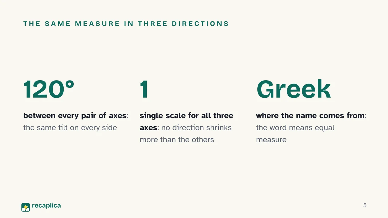
    Isometric drawing is a method for representing a three-dimensional object in two dimensions, widely used in technical and engineering drawing. The three coordinate axes are projected shortened by the same amount, and the angle between any pair of them is always 120°. The word “isometric” comes from Greek and means equal measure: the scale along each axis of the projection matches the other two.

    It is one of three ways to build an axonometric projection, alongside dimetric and oblique projection: the general picture of axonometric projection, with the rules shared by all three, is the starting point for seeing where this particular case fits. Isometric drawing is a variant of orthographic axonometric projection: an orthographic projection is called isometric whenever its three axes form equal angles with one another.

    Compared with a method that draws an object view by view, isometric drawing shows the whole object in a single image, keeping every face recognisable at once. There is no shrinking toward vanishing points here, the way there is in perspective drawing: an isometric object stays the same size at any distance from the viewer.

    Building it: axes at 120°

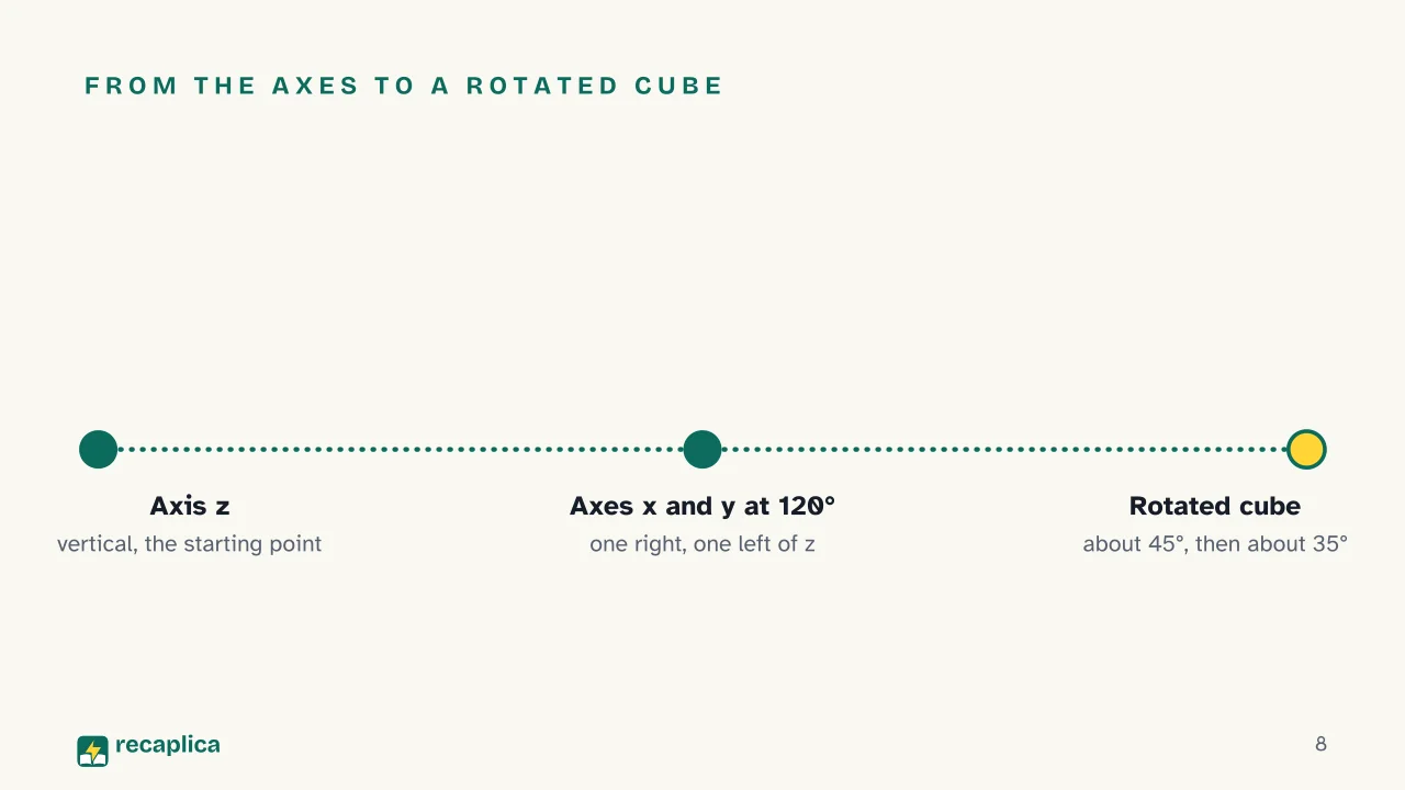
    The construction starts from the vertical axis z. The other two axes, x and y, are drawn tilted 120° from z: one to the right, one to the left. This way, the three perpendicular edges of the object are projected at equal axonometric angles, and the angle between each pair of projected edges stays at 120°.

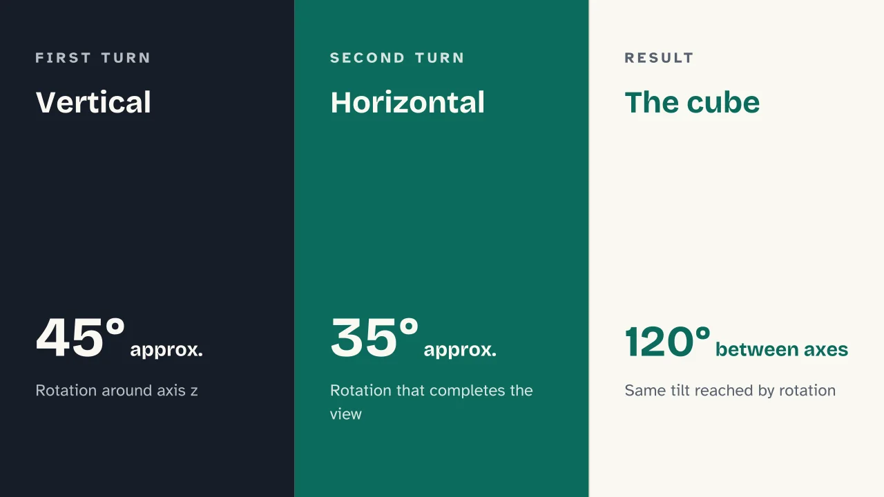
    A classic alternative construction starts from a cube in its normal position and rotates it about 45° around the vertical axis, then about 35.264° around a horizontal axis. This rotation reaches the same 120° angles by moving the object itself, rather than by drawing the axes first.

    The scale factors along the three axes are identical to one another — hence the name iso-metric, equal measure in every direction. No single axis gets special treatment, the way one does in oblique projection.

    From the cube to the drawing: a worked example

    Worked example: to draw a cube in isometric projection, start by drawing the vertical axis z, then the axes x and y tilted 120° to the right and left. The cube’s edge length is marked off on all three axes, equal everywhere because the scale is identical in every direction. A classic way to reach the same result by rotation is to tilt the cube until it rests on a lower front vertex, with the cube’s solid diagonal perpendicular to the plane of projection: the three visible faces then appear as three identical rhombuses around the vertex closest to the viewer.

    A cube is the simplest case because all its edges are equal and perpendicular to one another: the same construction rules apply to any solid, including the ones covered in solid geometry, but a cube makes the 120° symmetry obvious at a glance.

    Isometric drawing versus true isometric projection

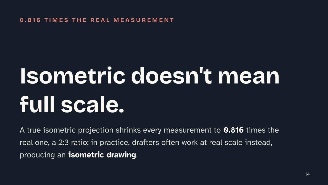
    There is a distinction that often gets lost in practice: a true isometric projection, at real scale, shrinks every length by a factor of 0.816 compared with the real measurement, a ratio of 2:3. A drawing built with that reduction is called a true isometric projection.

    On the drafting table, though, it’s common to mark off the object’s real measurements instead of the shrunk ones: the isometric drawing produced this way — not a true isometric projection — comes out slightly larger than the real object, but the proportions between the axes stay correct. It’s the more common choice in technical manuals, since it skips the reduction calculation without changing the shape of the drawing.

    Isometric, dimetric, oblique: the differences

    The three families of axonometric projection part ways on how they treat the axes.

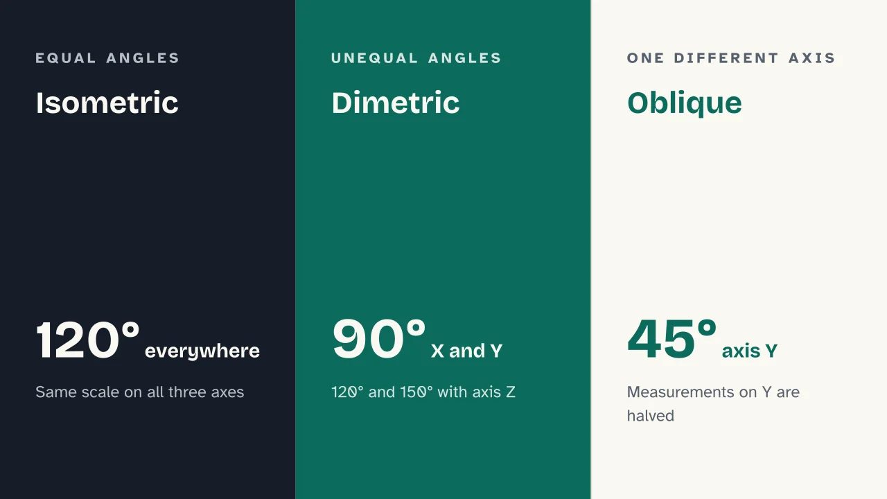
    TypeAngles between axesHow measurements are treated
    Isometric120° between every pairIdentical scale on all three axes
    Dimetric90° between X and Y, 120° and 150° with ZUnequal angles between axes
    Oblique90° between X and Z, Y tilted 45°Measurements on Y are halved by convention

    In oblique projection, the plane of projection stays parallel to one face of the object; in isometric drawing, it is tilted equally relative to all three principal planes instead. It’s this symmetrical tilt, more than the angle itself, that makes isometric drawing the most regular of the three.

    Where it’s used

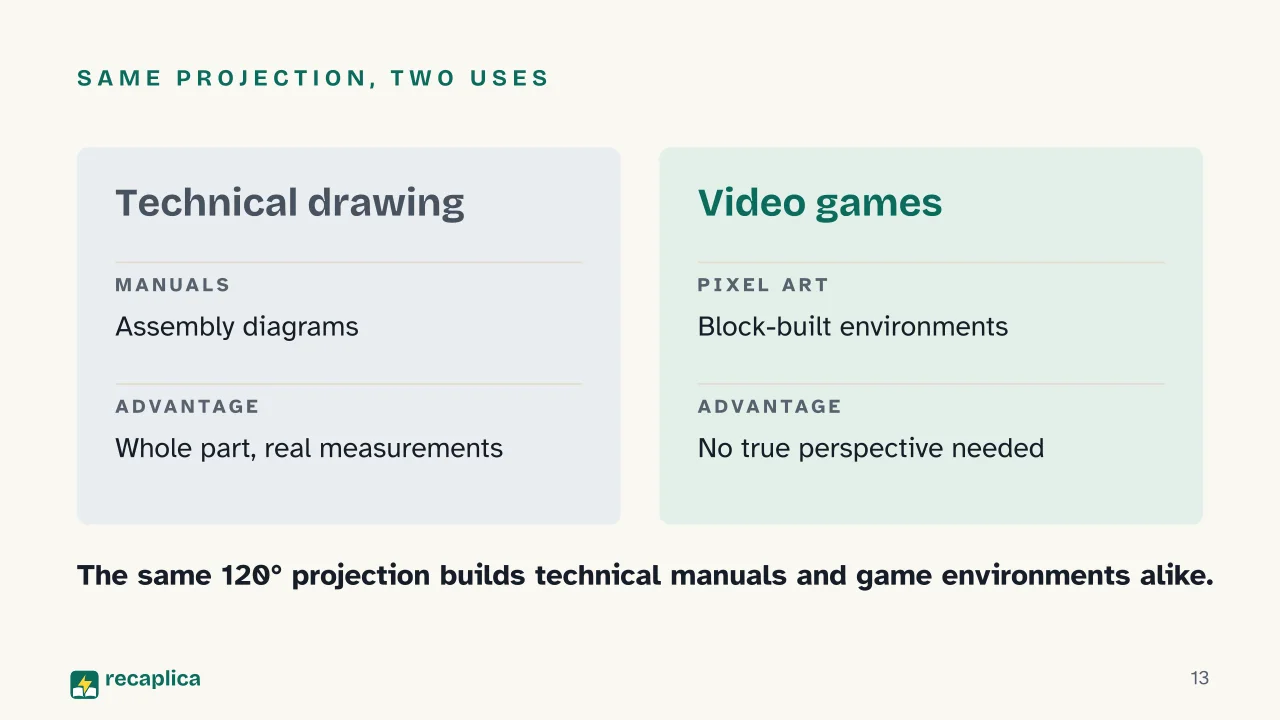
    Isometric drawing shows up in mechanical manuals, assembly diagrams and industrial drawings, wherever a whole part needs to be shown without losing the proportions between its pieces. The same parallel projection, with the same 120° angles, also turns up in video game graphics and pixel art, used to build readable three-dimensional environments without calculating a true perspective. Anyone working with solids of revolution finds isometric drawing a convenient way to sketch their development, since the equal scale on all three axes introduces no distortion that would make the solid’s curve hard to read.

    Slide deck

    Slides ready to download and make your own in PowerPoint or Google Slides, with speaker notes. Pick the Flash cut or the Full one.
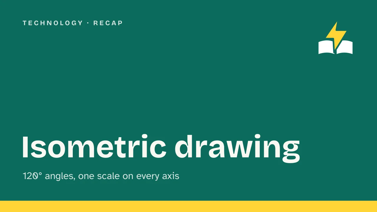
    Slide 1 of the presentation on Isometric Drawing: Isometric drawingSlide 2 of the presentation on Isometric Drawing: A cube drawn this way never looks distorted. Why not?Slide 3 of the presentation on Isometric Drawing: From the angle to the finished drawingSlide 4 of the presentation on Isometric Drawing: Chapter 01: What it isSlide 5 of the presentation on Isometric Drawing: The same measure in three directionsSlide 6 of the presentation on Isometric Drawing: Do isometric objects shrink as they move further away?Slide 7 of the presentation on Isometric Drawing: Chapter 02: How to construct itSlide 8 of the presentation on Isometric Drawing: From the axes to a rotated cubeSlide 9 of the presentation on Isometric Drawing: Vertical · Horizontal · The cubeSlide 10 of the presentation on Isometric Drawing: Chapter 03: Comparing the threeSlide 11 of the presentation on Isometric Drawing: Isometric · Dimetric · ObliqueSlide 12 of the presentation on Isometric Drawing: Chapter 04: Where it's actually usedSlide 13 of the presentation on Isometric Drawing: Same projection, two usesSlide 14 of the presentation on Isometric Drawing: Isometric doesn't mean full scale.Slide 15 of the presentation on Isometric Drawing: Does an isometric object's size change with distance?Slide 16 of the presentation on Isometric Drawing: Now for the review
    Flash10 slidesThe essential thread, to present in classFull16 slidesEvery chapter and the deeper detail

    Common myths

    • ✗ Myth Many people think isometric drawing is just "a 3D sketch done by hand," without a precise rule behind it.

      ✓ Reality There is a fixed geometric construction behind it: three axes at an exact 120° and the same scale on each one. A technician drawing an isometric screw in Milan and one doing the same in Tokyo end up with the identical angle between the axes, because the rule leaves no room for interpretation.

    • ✗ Myth The isometric-looking drawing you see in a technical manual is often assumed to be a true isometric projection.

      ✓ Reality In most cases, the drafting table uses the object's real measurements rather than the shrunk ones: the result is an isometric drawing in the practical sense, slightly larger than a true isometric projection, which instead applies a 0.816 factor to every length.

    • ✗ Myth A common assumption is that isometric and dimetric are just two names for the same thing, since in both cases objects don't shrink with distance.

      ✓ Reality The two part ways on the angles: in isometric drawing all three angles between the axes equal 120°, while in dimetric projection the angle between X and Y stays at 90° and the other two open up to 120° and 150° — a different construction, even though both belong to the same family of orthographic axonometric projection.

    Mind map

    Drag the background to move around and the nodes to reposition them; use − and + to collapse and expand branches.
    Customize
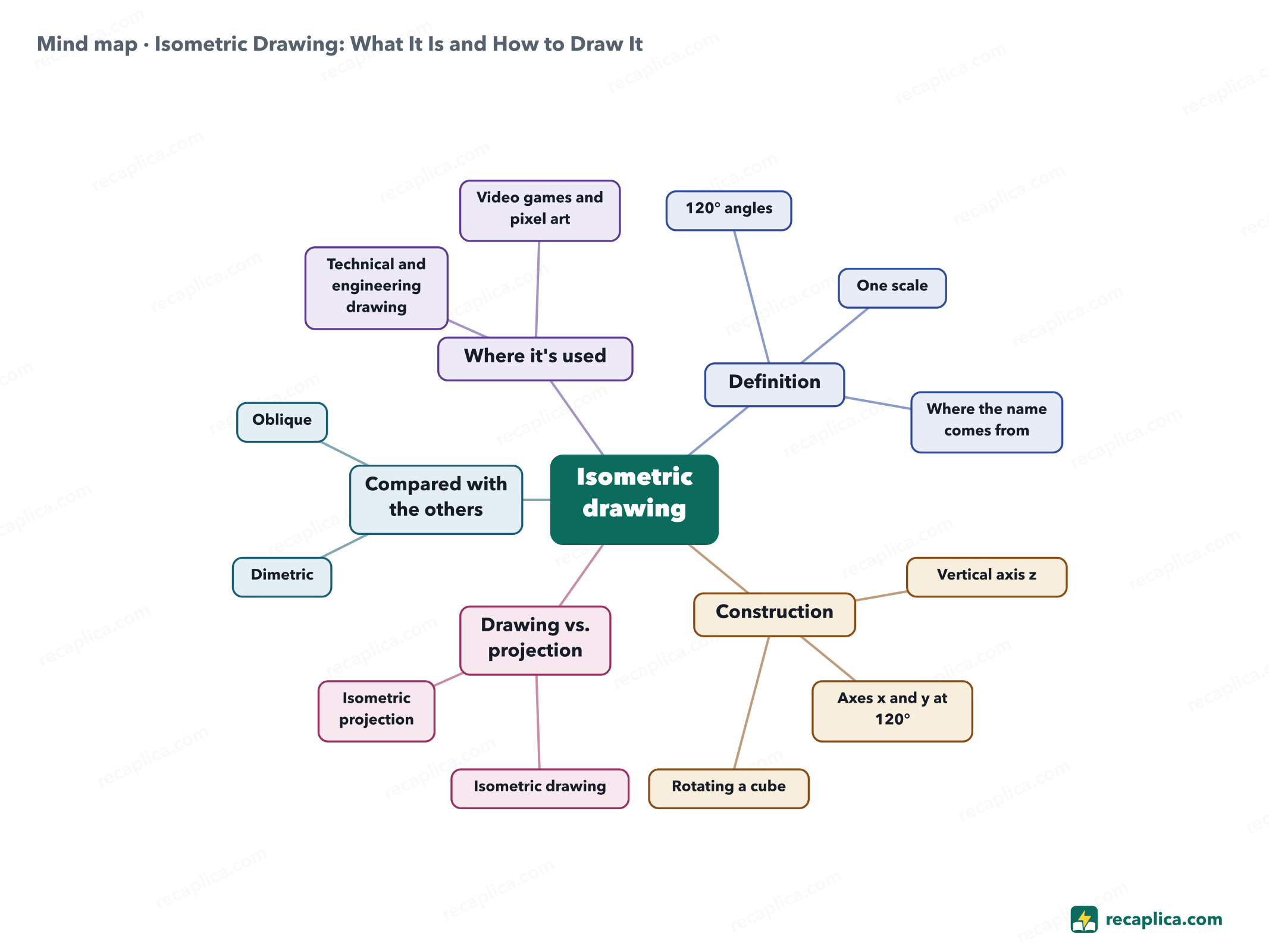
    Mind map: Isometric Drawing: What It Is and How to Draw It
    • Isometric drawing
      • Definition a three-axis projection with equal angles and equal scale
        • 120° angles between every pair of axes
        • One scale no direction is shrunk more than the others
        • Where the name comes from Greek for equal measure
      • Construction
        • Vertical axis z the starting point of the drawing
        • Axes x and y at 120° one to the right, one to the left of z
        • Rotating a cube about 45°, then about 35.264°
      • Drawing vs. projection
        • Isometric drawing real measurements, practical use
        • Isometric projection 0.816 scale, a 2:3 ratio
      • Compared with the others
        • Dimetric unequal angles, 90°/120°/150°
        • Oblique one axis at 45°, measurements halved
      • Where it's used
        • Technical and engineering drawing
        • Video games and pixel art

    Quiz: test yourself

    Answer the questions to check what you have learned: you get instant feedback and a short explanation.

    Grade 0/10 0/5
    1 How large is the angle between each pair of axes in isometric drawing?

    The three axes always meet at 120°: it is the feature that sets isometric drawing apart from the other orthographic axonometric projections.

    2 Where does the word "isometric" come from?

    The term comes from Greek and signals that the scale factor is the same on all three axes, with no exceptions.

    3 What happens to an object's size in an isometric projection as it moves further from the viewer?

    Unlike perspective drawing with its vanishing points, isometric projection keeps dimensions unchanged regardless of distance.

    4 What is the main difference between an isometric drawing and a true isometric projection?

    In practice, drafters often work with real measurements, producing an isometric drawing; applying the 0.816 factor to every length instead yields a true isometric projection.

    5 In dimetric projection, are all the angles between the axes equal, just like in isometric drawing?

    In dimetric projection the angle between X and Y stays at 90°, while the other two axes form 120° and 150° angles with Z: they are not all equal, unlike in isometric drawing.

    Answers: 1-B · 2-B · 3-B · 4-A · 5-B

    Flashcards

    Tap the card to flip it and check whether you remember the answer, then move to the next one.

    1 / 8

    Explain it in your own words

    The ultimate test: if you can explain it in simple words, you've truly understood it. Write your explanation, then compare it with the Recap.

    Your explanation is saved only on this device.

    Isometric drawing represents a three-dimensional object on a flat sheet without distorting its proportions along any of the three axes. The coordinate axes always meet at 120° angles, and the scale is identical along each one — hence the name, which comes from the Greek for equal measure. It is built either by starting from a vertical axis and drawing the other two tilted 120° apart, or by rotating the object roughly 45° and then about 35° relative to the viewer. It is the most common type of axonometric projection in technical drawing, and it also shows up in video games and pixel art.

    Frequently asked questions

    Does isometric drawing distort an object's measurements?

    It shrinks them equally on all three axes, but not asymmetrically: the scale stays identical in every direction, unlike in oblique projection.

    What is the difference between isometric drawing and perspective drawing?

    In perspective drawing, objects shrink as they move toward vanishing points; in isometric drawing, dimensions stay constant regardless of distance.

    Why do isometric drawings often use real measurements?

    Because it simplifies the practical work: the drawing comes out slightly larger than a true isometric projection, but the proportions between the axes stay correct.

    Is isometric drawing only used in technical drawing?

    No: the same parallel projection also shows up in block-built video game environments and pixel art, besides industrial and mechanical drawings.

    Sources

    • Isometric projection
    • Assonometria isometrica
    • Le ASSONOMETRIE
    • Isometric Projection

    Every Recap goes through an independent review before publication.

    Every evening, the day's new Recaps on our Telegram channel. Join the channel →

    Keep learning

    • Technology Monometric Axonometric Projection: What It Is and How to Draw It Monometric axonometric projection is an oblique projection used in technical drawing to represent a three-dimensional object on a flat sheet. In the scheme most common in Italian school curricula, the vertical axis stays upright, while the other two axes are drawn at 30° and 60° from the horizontal, with a 120° angle between the x-axis and the vertical axis. What sets it apart from cavalier axonometric projection is that the object's measurements are transferred onto all three axes without any reduction, at true scale. In Italian technical-drawing vocabulary the name carries some genuine uncertainty: some sources treat it as a synonym for isometric projection, while other textbooks present it as a separate category. Read the Recap →
    • Technology Axonometric Projection: Definition and How to Draw It Axonometric projection is the descriptive-geometry method for drawing a three-dimensional object on a flat sheet in a single view. Unlike perspective, parallel lines stay parallel, so distances can be measured straight off the drawing. Several variants exist, isometric, trimetric, dimetric, oblique (cavalier), which change the angles between the axes and how each one shortens the measurements. The type most used in school technical drawing is isometric, with 120° angles between the axes, built from an isometric scale that carries the correct lengths onto the paper. Engineers and architects also rely on it to show the shape and structure of a building in one diagram. Read the Recap →
    • Technology What Is Orthographic Projection? How to Draw an Object in Three Views Orthographic projection is how technical drawing shows a three-dimensional object using several flat views instead of one: a top view, a front view, and a side view. Each view comes from projecting the object onto a plane set at a right angle to the direction you're looking from, and together the three views carry enough information to reconstruct shape and size without guessing. The United States uses third-angle projection, which places each view on the same side as the face it shows; most of the rest of the world, including Europe, uses first-angle projection, which places it on the opposite side. The method traces back to Gaspard Monge's two-plane projection, written up in the eighteenth century and still the basis of geometric drawing today. Read the Recap →

    recaplica

    Clear in 30 seconds, yours in 10 minutes.

    Recaps Mind maps Request a Recap Telegram channel Mind map maker Our method About Privacy & cookies Legal notes & terms of use

    © 2026 Recaplica · A project by Curi S.r.l. — VAT IT05472000750

    Statistics, only if you say so

    To learn which Recaps help most we would use Google Analytics, with aggregate, anonymous data. It starts only with your OK, and you can change your mind anytime. Privacy policy